|
INCREASING the DISPLACEMENT of the BUICK OLDS 215 and the ROVER 3.5 TO 4.6 LTR. ALUMINUM V-8
©Dan LaGrou
If you want more than 266 inches the way to go is procure a 3.701 bore Rover block. These blocks come in two versions; early blocks built from 1989 to 1995 have 2 bolt-main caps and 2.300 main bearing journals. They are good to 6500 rpmπs (street use) normally aspirated. If the engine is to be run over 6500, see track time, be supercharged, turbo charged or see nitrous the 1996 and newer cross-bolted block should be used. This block has a beefier lower end, 2.500 main bearing journals and cross bolts through the skirt of the block. One bad feature of the 1996 and newer blocks is that there are no undersize bearings available. It must be align bored about .022 to accept Buick 300 main bearings. By installing a 300 crank in a 3.701 bore block that has been honed .010 oversize the displacement comes out to 293 cubic inches. 3.701 bore Rover blocks have a cylinder liner that is .072 thick, maximum bore is 3.740. Boring and re-sleeking all 8 cylinders on any V-8 engine is not cost effective. If 300 cubic inches of displacement is not enough, the least expensive way to go is by building an all aluminum small block Chevy or Ford. Big displacement engines can be built based on late 4.60 Rover short blocks but I feel they are also not cost effective. They are quite rare as a rebuildable core, quite expensive new and require more crank modification than Buick 300ns. In all, any 3.701 bore Rover block with a 300 Buick crank, along with early 5.66 rods or Chevy rods and Ford 255 pistons, will give you the best "Bang for your Buck". Two different displacements can be achieved after the installation of a Buick 300 Crankshaft. They are dependent upon which block is use:
The engine stroking process consist of six basic phases:
Final engine assembly differs very little from that of a standard rebuild. SECTION ONE: CRANKSHAFT PREPARATION The Buick 300 crankshaft differs dimensionally from the 215/3.5 to 4.6 crankshaft in three significant ways:
*Can be offset ground to about 3.375≤
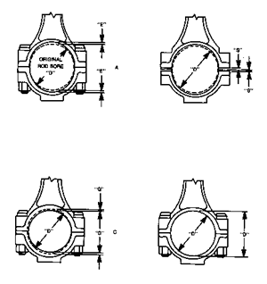
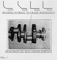
The overall length: The 300 crank is .56" longer than the one it is replacing. The extra length moves the flywheel farther from the back of the block, requiring a specially machined flywheel in order to fit the bell housing and to align with the starter. The rear main oil seal fit. The stock 215/3.5 rear main seals will not align on the 300 crankshaft. A special adapter is necessary to install a seal in the block, correctly positioned to index on the crank. (D & D No. 215-300-S) Historically, the modified rear main seal has been adapted by the fabrication of a large seal "holder" which required machining of the rear of the block. D & D Fabrication has developed a reliable rear main seal adapter that can be installed by merely drilling two small holes in the block. This process is explained in detail in the "Engine Assembly" section. Hundreds of aluminum V-8πs have been stroked with the Buick 300 crankshafts. Many have gone into high performance car, marine, and airplane applications and the crankshaft has proven more than adequate. For a road going engine that will not be used over 6500 rpm, the crank will require a minimum of preparation, aside from the reduction of the main bearing journal diameter. The required crank work consists of: Having the main bearing journal ground and polished from 2.5" to 2.3". Note: When you pick up the finished crankshaft at the machine shop, check the points at which the main bearing and rod journals intersect the webs. The intersection should be well radiused. This juncture is one of the most highly stressed areas on the crank and cracks will normally start wherever there is a sharp angle or scratch in the metal surface. (See Illus. 1) Having the rod journals checked for proper diameter and ground undersize, if necessary, to clean them up. Install a new pilot bushing. If the pilot bushing is not renewed and is worn, the transmission input shaft as well as the clutch friction disc will wobble. This will manifest itself in a chattering clutch, hard shifts, and other shifting problems. A new pilot bushing is very cheap and a new one should be considered mandatory. The trick to removing the old bushing is to get a big wad of heavy grease on your finger and pack it behind the bushing and in the bushing bore. Place an old transmission input shaft, or any metal rod which fits closely, into the bushing, Give the end of the rod a sharp rap with a hammer, and the hydraulic action of the grease will force the bushing from the crank. Check the crank for straightness. This can be done either before machining or after. If done before, the check can be made by installing the crank in a lathe or a jig that holds both ends centered. A dial indicator is placed on the center main bearing journal and the crankshaft slowly rotated. The journal should not indicate more than .002" lateral travel. If the crankshaft has been machined, it can be installed into the block, using only the front and rear main bearings and caps. Lubricate the bearings and torque the caps to spec. Place a dial indicator on the center main bearing journal and spin the crankshaft. Again, the indicator should show no more than .002" total lateral runout. If the crankshaft is slightly bent, all is not lost. Any competent machine shop can straighten a bent crankshaft relatively easily.
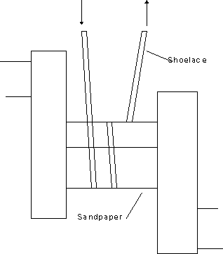
There are some optional operations that can be performed either at home or by the machine shop. These are not absolutely necessary for a road engine, but fall into the categories of either insurance or blueprinting. By insurance, I mean that the additional inspections may prevent the machining of a crankshaft that proves to be unusable. Blueprinting means taking extra care to bring the part as close to perfect as possible. These include: Magnafluxing - The Buick 300 crankshafts that are being used are 30+ years old and the operating history of a particular crank is seldom available. It is rare, but possible, that a crank is machined and installed only to fracture in service because of a pre-existing crack. Magnaflux inspection detects cracks and surface imperfections by the use of a magnetic powder and a Magnaflux electric magnet. The powder is dusted onto the crankshaft and a magnetic field set up on the crankπs surface with the electric magnet. Surface cracks and flaws interrupt the magnetic field and force the powder to form lines along the imperfection. All competent machine shops can perform Magnafluxing of engine components. Chamfering of the Oil Passages - When the oil passages are drilled into the crankπs main and rod journals, a sharp edge with burrs may result when the drill breaks through the surface. This condition may also arise when the main journals are ground down. These rough edges should be chamfered with a small grinding stone mounted on a drill, die grinder, or Dremel tool. Just a mild chamfer need be made, being very careful not to scratch the journal surface. The chamfer also furnishes a small reservoir of oil that can aid in the distribution of oil across the bearing surface. The machine shop performing the grinding of the main journals can usually chamfer the oil holes at a nominal fee. After chamfering, the journals must receive a polish to remove any burrs. If the chamfering is done at home, the journals can be polished by cutting a new, clean piece of 600 grit wet/dry sandpaper the width of the journal and long enough to wrap around the journal at least 1-1/2 times. Lubricate the sandpaper with solvent; wrap a shoelace around the paper and pull the lace ends alternately up and down. (See Illus. 2). Deburring the Crankshaft - Any cast crankshaft, including the Buick 300, has some amount of casting flash and sharp edges on the counterweights. Excessive flash and sharp edges can be smoothed out with heavy grit sanding disc or a small grinder. Deburring will prevent any small pieces of metal from breaking off of the crank and dropping into the oil pan. Secondly, cracks usually originate on a sharp edge or some imperfection on a metal surface. Deburring reduces the number of likely fracture origination sites.
Illus. 2
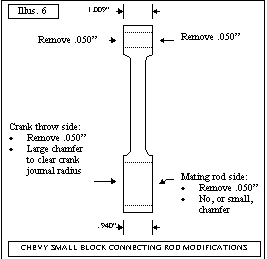
Chasing the Threads - Because the crank is used and also has gone through a lot of handling, it is good practice to chase all of the threads with a lubricated tap to dislodge and remove any crud or metal chipsCross Drilling - The machine shop may suggest cross drilling the crankshaft if they know that it is going into a modified engine. On most stock crankshafts, a single hole or drilled passageway connects each main bearing journal and the adjacent rod journal. As the crank rotates, one end of this passage passes over the oil groove in the lower main bearing shell, picking up a fresh charge of pressurized oil and feeds it to the rod journal. Drilling one or two additional holes in the main journal, intersecting the original oil passage can augment this system. (Hence "cross drilling"). Now the main to rod journal passage is exposed to a constant supply of pressurized, as at least one oil passage is exposed to the bearing shell oil groove at all times. Cross drilling of the Buick 300 crank may be fun to brag about at the next car meet, but unless the engine is being built for high rpm endurance events, it is a waste of money. SECTION TWO: CONNECTING RODS For almost all street and 4.2 applications, properly inspected and prepared stock connecting rods work fine. Buick/Olds 215, the Rover 3.5 and 3.9 rods are very similar. (See chart below) Another connecting rod which has been often used in stroking the aluminum V-8 is a pre-π67 Chevy small block rod. This rod has a 2" big end diameter which mates with the Buick 300 crank. Itπs 5.7" c/l to c/l length is also very close to the Buick/Olds/Rover rods. This longer length may be useful, depending on the piston, to achieve the desired compression ratio. Use of the Chevy rod requires additional machining however, as the stock Chevy rod is too wide to fit on the Buick 300 crank. (See Illustration 6)
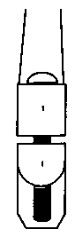
As with the crankshaft there are several mandatory operations plus some which, while not being absolutely necessary, can reduce the chance of rod failure. The "must-do" steps are: 1. Make sure that when the rods are removed from the engine that each rod and end cap are marked so that they are always matched to their original mate. (See Illus. 3) 2. Bead blast the rods to make sure they are absolutely clean. 3. Have the rods shot blasted. Shot blasting bombards the rod with very small ball bearings that compress the con rodπs surface. This induces permanent compressive forces on and just under the metal surface, greatly impeding the formation of cracks. 4. Have the small ends reamed and honed to fit the wrist pin that is going to be used. The wrist pin diameter will be dependent on the type piston. Make sure the machinist hones the small end out to itπs final dimension. Some shops may try to merely ream to the finished size. Reaming is not a precision operation and cannot achieve the precise dimensioning required for proper fit of the wrist pin. The Buick/Olds/Rover and Chevy connecting rods all are designed for pressed wrist pins that are held rigidly in the rods and do not ride in a bushing. The small end should have a wrist pin interference clearance of .0015 - .0020" which will allow the pins to be pressed into position. The edges of the small end should be chamfered or debarred, after honing, to remove sharp edges or burrs that may interfere with pin installation.
5. Resize the big ends. After undergoing millions of cycles, used connecting rod big ends usually become oval, with the larger diameter parallel with the rod beam. This distortion prevents the con rod bearings from fitting properly and can lead to oil pressure loss, rapid bearing wear or a spun bearing. The rod big ends should be resized by a competent machine shop. The machinist will:
As with the crankshaft, there are a couple of procedures that can be taken to add a little insurance against rod failure. These are:
Illus. 4
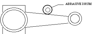
Magnafluxing - Prior to having any work done of the rods, they can be Magnafluxed to check for possible cracks. The machine shop can also check the rods for straightness quickly and inexpensively. Polishing - As noted in the crankshaft section, a polished metal surface is more resistant to crack formation than a rough one. In order to minimize the chance of rod cracks starting, the rod beams can be debarred and polished. This can be done easily at home, prior to taking the rods to the machine shop. The main purpose here is to reduce the height of the casting mark running along the rod beam and smooth the beamπs side. Be careful only to remove the casting ridge and not to actually remove wall material from the beam. The first step is to install the rod caps, bolts and nuts. Tighten the nuts snugly but they do not have to be torqued or really very tight. (A note - never tighten down rod bolts and nuts while holding the rod by itπs beam. The beam can be twisted fairly easily. Always clamp the big end into a vise using padding, brass or aluminum jaw pads.) Using a bench grinder, carefully grind off most of the casting ridge from the beam sides. Then, using an abrasive drum in a die grinder or drill, dress down the rest of the ridge and blend it into the beam wall. A high polish in not necessary, only a smooth one. Carry the smoothing up and over the small ends. (Another note - When polishing with the abrasive drum, always keep it at a 90∞ angle to the rodπs length. Any microscopic scratches from the polishing should travel parallel with the beamπs length. (See Illus. 5 above). The sharp edges around the rod bolt heads and the nuts can be broken and smoothed with a small, fine file or sandpaper. Illus. 5
SECTION THREE: FLYWHEEL The stock BOP 215 or Rover flywheels will not bolt onto the 300 crankshaft and the stock Buick 300 flywheel is too large to fit in the BOP/Rover bellhousings. Add to these sad facts that even if one of these flywheels would fit the crank and clear the bellhousing, the .56" rear offset of the 300 crank would position the flywheel out of the reach of the starter gear. Therefore, a custom flywheel is necessary. D & D have upgraded to a fully custom-machined flywheel specifically engineered for the stroked BOP/Rover application. The flywheel Part No. is 467025. If an automatic transmission is desired, D & D also has flexplates modified to adapt many automatic transmissions to the stroker aluminum V-8
SECTION FOUR: BALANCING Everyone is familiar with the effects of an unbalanced moving load. A washing machine on the spin cycle will sometimes literally "walk" across the floor if all of the clothes have moved to one side of the drum. An unbalanced tire can cause the steering wheel to vibrate so badly that it numbs your hands. These are occurring at only a few hundred revolutions per minute. Now, take an unbalanced engine spinning at 6000 rpm. The forces acting to tear the motor apart are tremendous. A single ounce has a dynamic weight of over 700 pounds when it is located on a crankshaft counterweight. The importance of accurate engine balance cannot be emphasized too much. Imbalance will cause premature failure of the crank, connecting rods, wrist pins, or pistons. It can also cause very rapid bearing wear and failure. There are two major forces acting on the engineπs internal parts. The first is rotational force that acts primarily on the crankshaft, con rod big end bearings. Reciprocating force is the result of the straight line travel-stop-reverse travel motion experienced by the pistons, rings, wrist pins, and con rod small end bearings. The connecting rods see both movements as they attach the reciprocating pistons to the rotating crankshaft. Balancing attempts to bring these forces into harmony, primarily by equalizing the weight of the various reciprocating components (each piston, ring, wrist pin, con rod and con rod bearing combination equalized with the other seven in the engine), and by adjusting the weight of the crankshaft counterweights or balancing components. The Buick/Olds/Rover 215/3.5L engines are internally balanced as opposed to the Buick 300 that is externally balanced. Internal balancing means that there is sufficient mass in the crankshaft counterweights to balance out the reciprocating forces of the pistons, wrist pins, etc. Balance is achieved by adding or subtracting weight from the counterweights. To remove weight, material is ground or machined from the counterweight. To add any needed weight. The counterweights are drilled and a plug of Mallory metal is installed in the drilled hole. The crankshaft pulley can be changed without altering the engine balance, assuming it is in correct balance itself. Some engines, particularly those with large crankshaft stroke, must be externally balanced. This is because the crank counterweights cannot be made large (i.e. heavy) enough due to interference with the block or camshaft. In order to effectively balance the reciprocating and rotational forces, weight is added or subtracted to the flywheel and harmonic balancer. Obviously, these two items cannot be changed without necessitating a rebalancing of the engine.
It is sometimes possible to internally balance an originally externally balanced engine by reducing the weight of the reciprocating components i.e. lighter pistons, aluminum con rods, etc. The feasibility of this would have to be discussed with the engine balancing technician. When you take your motor into the machine shop for balancing, they will need:
The basic steps that the technician will go through to balance the components is: 1. Weigh all of the pistons, wrist pins, and connecting rods. The connecting rods will actually have both their big ends and small ends weighed separately. One end of the rod is supported horizontally on a hanger or fixture, while the other end is on a weighing scale. Then the rod is reversed and the opposite end weighed. All weight are taken in grams. (28.35 grams = 1 ounce) 2. The lightest piston and wrist pin will be determined and the weight of all of the other pistons will be reduced to match them. 3. The same process will be performed on the connecting rods, first the big ends, then the small ends. 4. Because the crankshaft cannot be spun with the con rods, pistons and pins attached, the technician clamps special weights, called bob weights, to the crankπs con rod journals. The bob weights replicate the weight of the reciprocating components imparted on the con rod journals. 5. The crankshaft is mounted in a balancing fixture and sensors are installed on the crankshaft ends. 6. The crank is spun and any vibration causes the crank ends, and the attached sensor, to oscillate. This oscillation is measured by the sensors and tells the technician where weight needs to be removed or added to the crankshaft counterweight in order to achieve correct balance (internally balanced engines) or weight. SECTION FIVE ≠ BLOCK PREPARATION Preparation of the block is very straight forward and follows standard rebuild procedures. The bulk of the work consists of cleaning the block and having the cylinders bored. The only procedure specific to a stroked 215/3.5 is the installation of an aluminum adapter to mate a custom rear main oil seal to the Buick 300 crankshaft. Some specialists machine the rear of the block in order to accept a rather large seal housing. Several years ago D & D Fabrications developed a very simple rear main seal holder which installs on the block, and rear main bearing cap, secured in place by roll pins. At the time of disassembly, the main bearing caps should always be marked so that they can be reinstalled to the same position on the block. If the caps were not marked or if new caps are used, the block and caps must be align bored. Using a hand grinder or file, de-burr any roughcast flashing in the lifter valley to prevent metal chips from dislodging and dropping into the oil pan. Have the cylinders bored as necessary to clean up the cylinder walls. The 215 can be overboard up to an absolute maximum of +.060", if you are very brave. On Buick/Olds engines, the block was cast around the cylinder sleeve, an imprecise method that often allowed the sleeve to slightly offset in the block. This presents the possibility that an overbore exceeding .030" may cause the sleeve to be excessively thin in places. The Rover block has itπs cylinder liners pressed into place after the casting is complete. Therefore the sleeves can be safely overboard to .040". The exact overbore will be dependent on which pistons are used and the piston manufacturerπs clearance recommendation. Because the aluminum block expands more than a cast iron one, the bore clearances should be kept on the close side of the manufacturerπs tolerances. Follow the recommendations of the piston ring manufacturer for the finish grit to which the cylinder should be final honed. Have the cam bearings replaced if necessary. With hot soapy water, and plenty of brushes, clean the block thoroughly. Pay particular attention to the oil galleries. After rinsing with clear water wipe the block and cylinders dry. Apply a coat of WD-40 or light oil to the cylinder wall to prevent rusting.
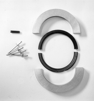
The rear oil seal adapter kit (D & D Fabrications Part No.215-300-5, Illus. 8) consists of: A precision machined two-piece aluminum seal spacer that installs into the rear main bearing cap and into the block. The only "machining" required is the drilling of two 3/16" diameter x 3/4" deep holes through one half of the adapter and into the rear main bearing cap. This is done using a hand drill
After the rear main bearing cap is drilled, the balance of the rear oil seal adapter installation can wait until engine assembly. SECTION SIX ≠ FRONT COVER The builder has a choice of using the BOP 215, the Rover, or the Buick 300 front cover; all are interchangeable. There are advantages or disadvantages to each option: The BOP 215 Cover The only advantage to retaining the 215 cover is that your accessory brackets may already be set up for it. If it is used, the archaic rope type front oil seal should be replaced with a modern one-piece rubber seal. D & D Part No. 45932 fits the bill and installs with no machining or modification of the cover. Another concern with the 215 front cover is that the cast-in timing marks will not correspond with the timing marks on the harmonic balancer. The procedure to rectify this problem is:
• With the crankshaft and the 300 cover installed, bring the #1 piston to TDC. The timing mark on the cover and the balancer should be precisely aligned The Rover front covers differ from model to model in that the Pre-SD1 covers use the same rope-type front oil seal as the BOP 215. D & Dπs rubber replacement seal works well in the early Rover cover. The later SD1 and Vitesse covers have the modern one-piece rubber seals. If the Rover covers are used, the timing mark on the balancer must be altered as for the BOP 215. The advantage of using the 300 cover is that the timing marks are in the correct position and the accessory mounting locations are sometimes better located for mounting of the alternator brackets and other accessories. The Buick 300 water pump is shorter than some stock Rover and BOP pumps, being about 3.625" in length from the back of the pump to the face of the pulley flange. D & D No. 1353-A water pump (also 3.625" in length) is a direct replacement for the 300 pump and can also be used on any 215 or Rover engine where clearance is a problem. ADDITIONAL STROKER MOTOR BUILDING TIPS A good all round camshaft for the stroked BOP/Rover engine is the Crower 50232 Street/Strip cam. This bumpstick yields good low-end performance with a manual transmission. The low manifold vacuum experience with this cam will not work well with an automatic transmission. For use with an automatic trans use Crower camshafts 50230 or 50231. All three camshafts are in stock at D & D. Starter Motors The BOP 215 starters came is two styles, one with an aluminum nose and one with a cast iron nose and larger outside diameter case. The cast iron nose version, because of itπs larger fields and armature, puts out more torque than the aluminum nose unit. Obviously, a stroked engine will place more demand on the starter. If problems are experienced with using an aluminum nosed starter, a cast iron nose unit may be needed. But this can be a problem in some engine conversion projects, such as an MG V-8 conversion, because the starter is cramped at best, and there might be interference problems with the cast iron nose unit. If more starter torque is required and the cast iron nose unit will not fit, D & D has modern small gear reduction starters to fit both the BOP 215 and Rover blocks. Spark Plugs For spark plugs, initially install the stock plugs. Then perform plug readings after the car is drivable to determine if a hotter or colder plug is needed. A point to remember when deciding what piston rod combination to use is to be sure that there is sufficient clearance between the piston and the plug tip. Check it before firing up the motor Recommended Reading Tuning the Rover V-8 by David Hardcastle. The most complete manual available detailing the Rover V-8 and itπs Buick/Olds 215 predecessor. Available from D & D Fabrications. Engine Blueprinting by Rick Voegelin. Practical and easy to read rundown of the entire engine blueprinting process including a complete chapter on calculating compression ratios. Available from S-A Design Publishing Co. 714-529-8239 (Brea, CA) |
|||||||||||||||||||||||||||||||||||||||||||||||
 illus.3